Step 3Body
The body is made of two halves of the arms with a base, a front part and holders. The procedure has five steps.
1. The battery holder
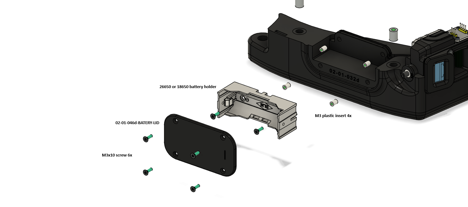
| Qty | Part | Note |
|---|---|---|
| 1 | Battery holder 26650 or 18650 | |
| 1 | 02-01-046d-BATERY-LID | Lid |
| 4 | M3 insert | |
| 6 | M3x10 screw | As in the drawing |
- Press the M3 inserts into the arm.
- Screw the battery holder on.
- Glue or secure the battery cables (see the chapter Electronics) and put the lid on.
2. The latch
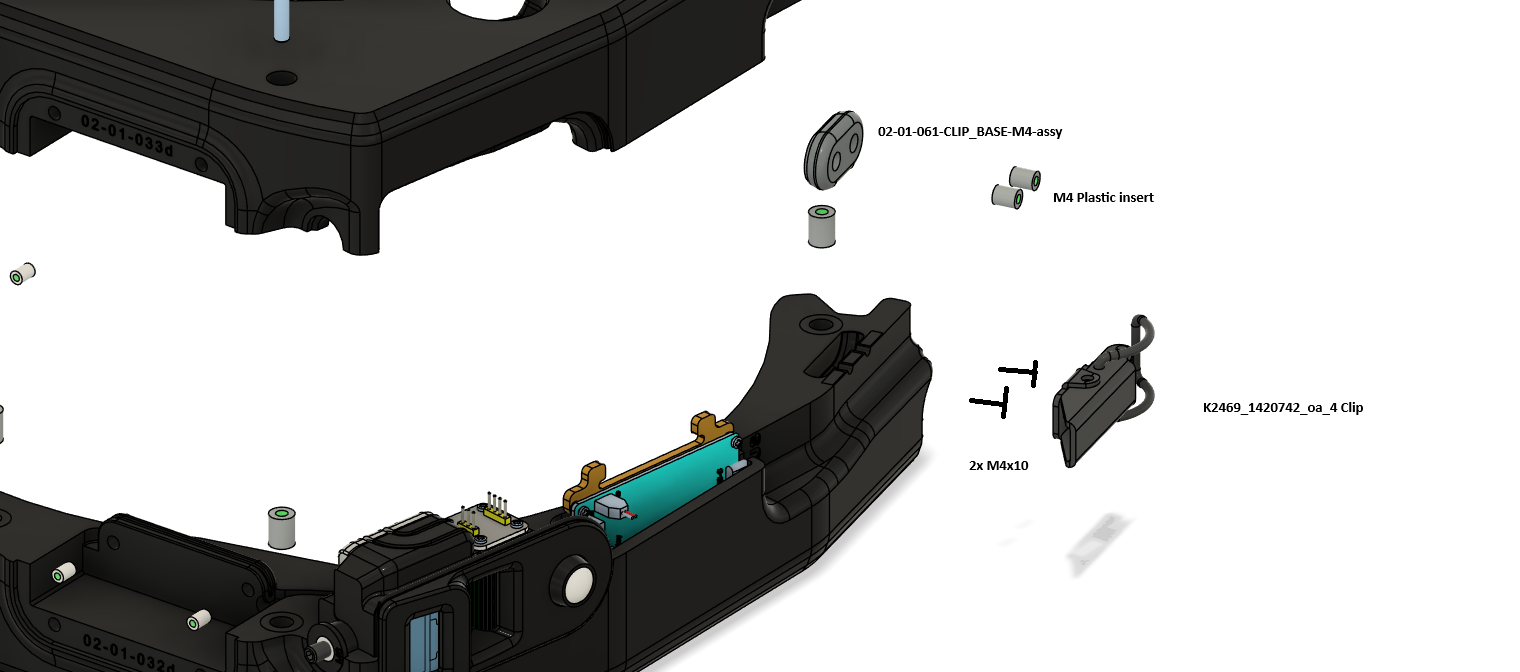
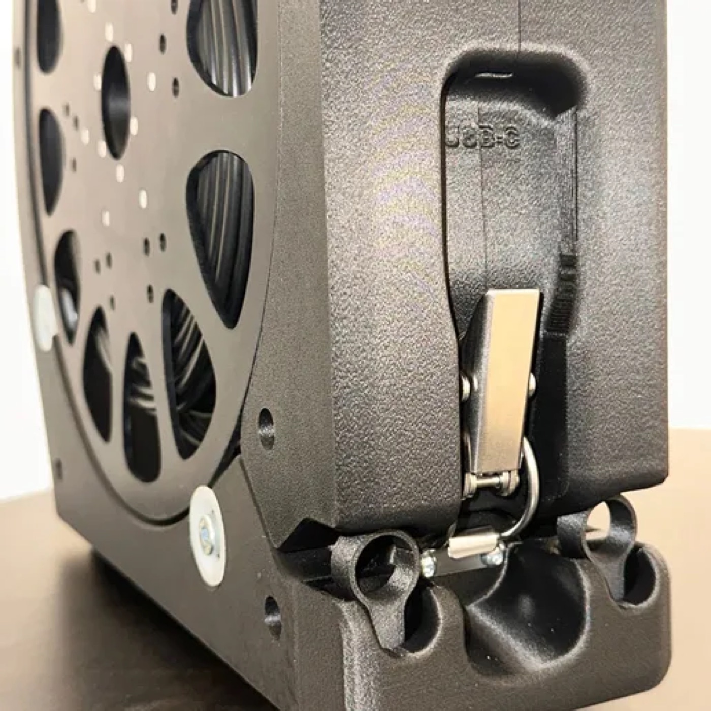
- Press in two M4 inserts.
- Put 02-01-061-CLIP_BASE-M4-assy and the latch K2469 in place and screw them on with two M4x10 screws.
3. The arms with the board
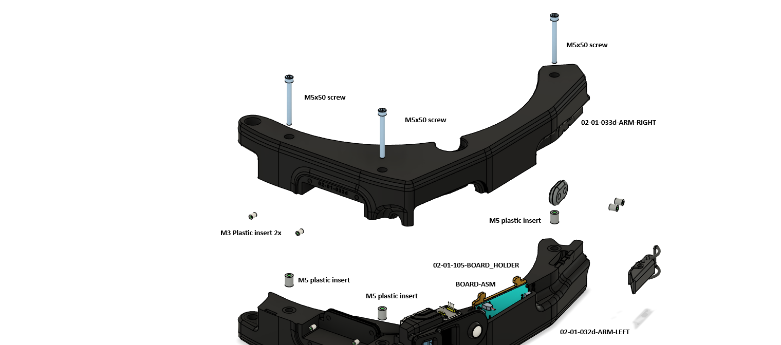
| Qty | Part | Note |
|---|---|---|
| 1 | 02-01-032d-ARM-LEFT | |
| 1 | 02-01-033d-ARM-RIGHT | |
| 1 | 02-01-105-BOARD_HOLDER with the board (BOARD-ASM) | See the chapter Electronics |
| 3 | Screw M5x50 | |
| 2 | M3 insert | |
| 2 | M5 insert | As in the drawing |
- Press in the M5 and M3 inserts.
- Put the board in its holder into ARM-LEFT and connect it before you join the arms.
- Put ARM-RIGHT on and pull the arms together with three M5x50 screws.
4. The front part
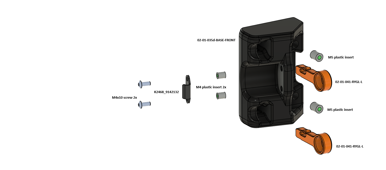
| Qty | Part | Note |
|---|---|---|
| 1 | 02-01-035d-BASE-FRONT | |
| 2 | 02-01-041-RYGL-L | Orange |
| 2 | M5 insert | For RYGL-L |
| 2 | M4 insert | For the catch |
| 1 | K2468_9142132 (catch) | See Buying |
| 2 | M4x10 screw |
5. The bases and the Packout holders
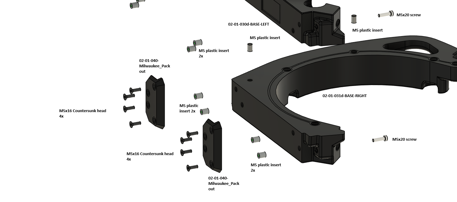
| Qty | Part | Note |
|---|---|---|
| 1+1 | 02-01-030d-BASE-LEFT, 02-01-031d-BASE-RIGHT | |
| 2 | 02-01-040-Milwaukee_Packout | Each to its base |
| 8 | M5x16 countersunk screw | 4 for each holder |
| 2 | Screw M5x20 | Joining the bases |
- Press the M5 inserts into the bases.
- Screw each Packout on with four M5x16 countersunk screws.
- Join the bases with the M5x20 screws.
The video opens after you buy this guide.See the plans →
The video opens after you buy this guide.See the plans →