Step 3Body
The body is made of two arms with a base, a front part and holders. Spooler Lite has no battery holder, no board and no wiring, the arms are simply joined.
1. Fit the latch
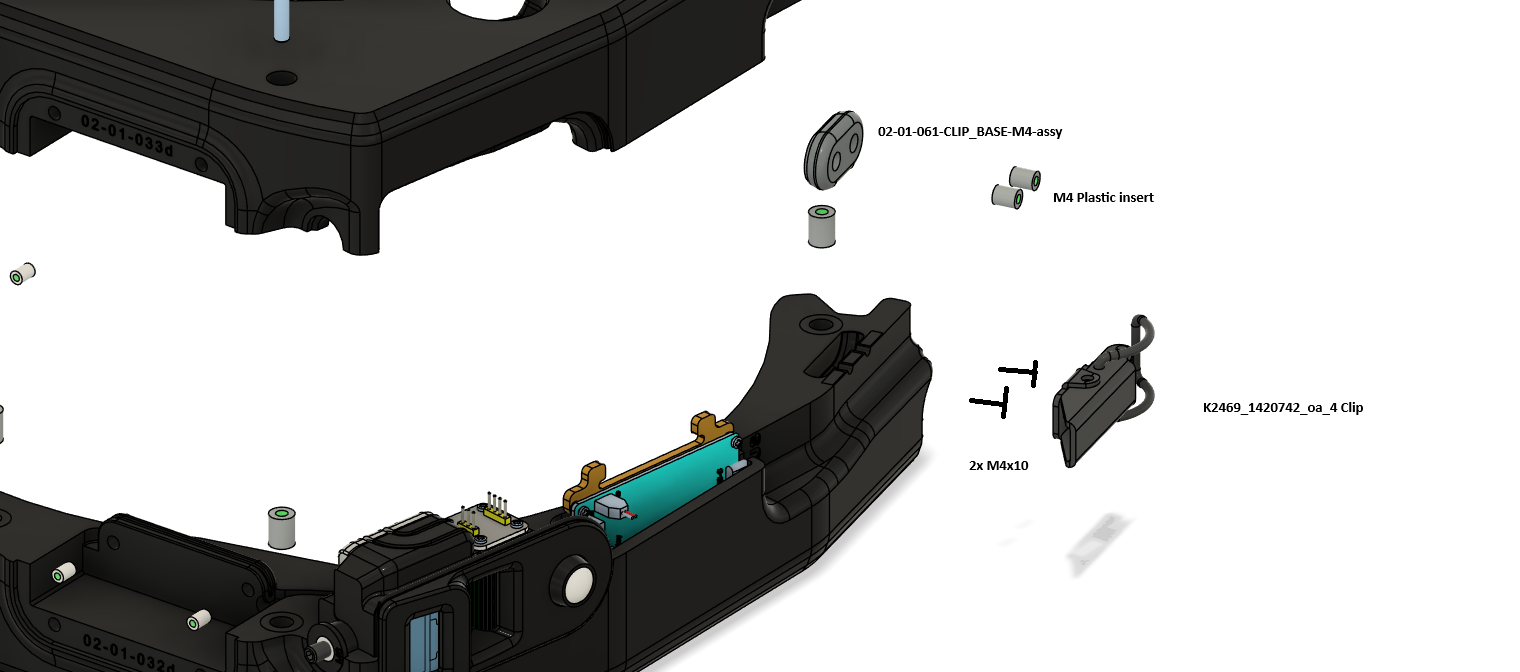
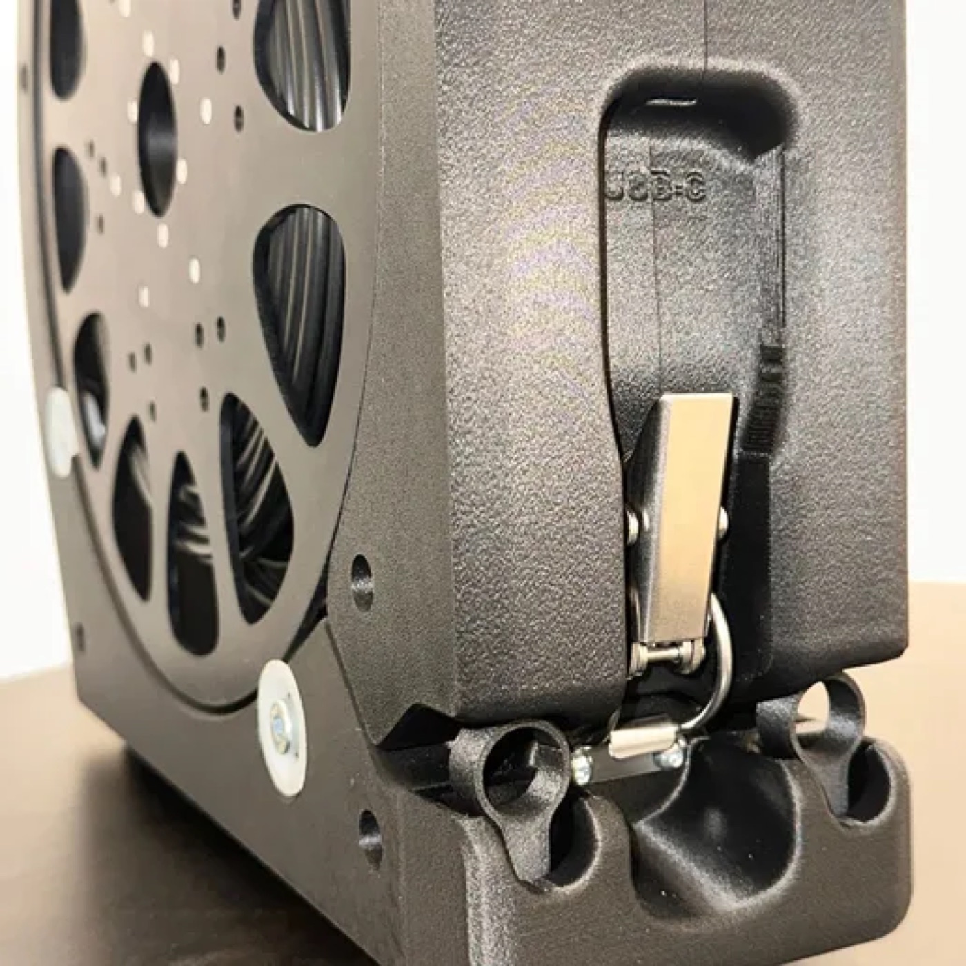
Press in two M4 inserts. Put 02-01-061-CLIP_BASE-M4-assy and the latch K2469 in place and screw them on with two M4x10 screws.
2. Join the arms
Press M5 inserts into the arms arm left and arm right. Put the arms together and pull them tight with three M5x50 screws. The arms have the same dimensions as 02-01-032d-ARM-LEFT and 02-01-033d-ARM-RIGHT of the Spooler Smart and differ only in small details.
3. Fit the front part
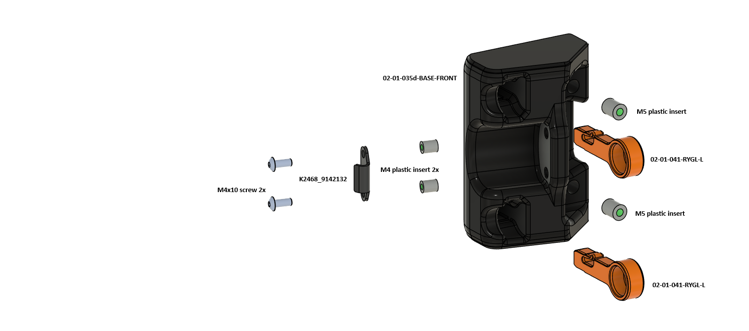
Press two M5 inserts for 02-01-041-RYGL-L (2 pcs) and two M4 inserts for the latch catch K2468 into 02-01-035d-BASE-FRONT. Screw the catch on with two M4x10 screws.
4. Screw on the bases and the Packout holders
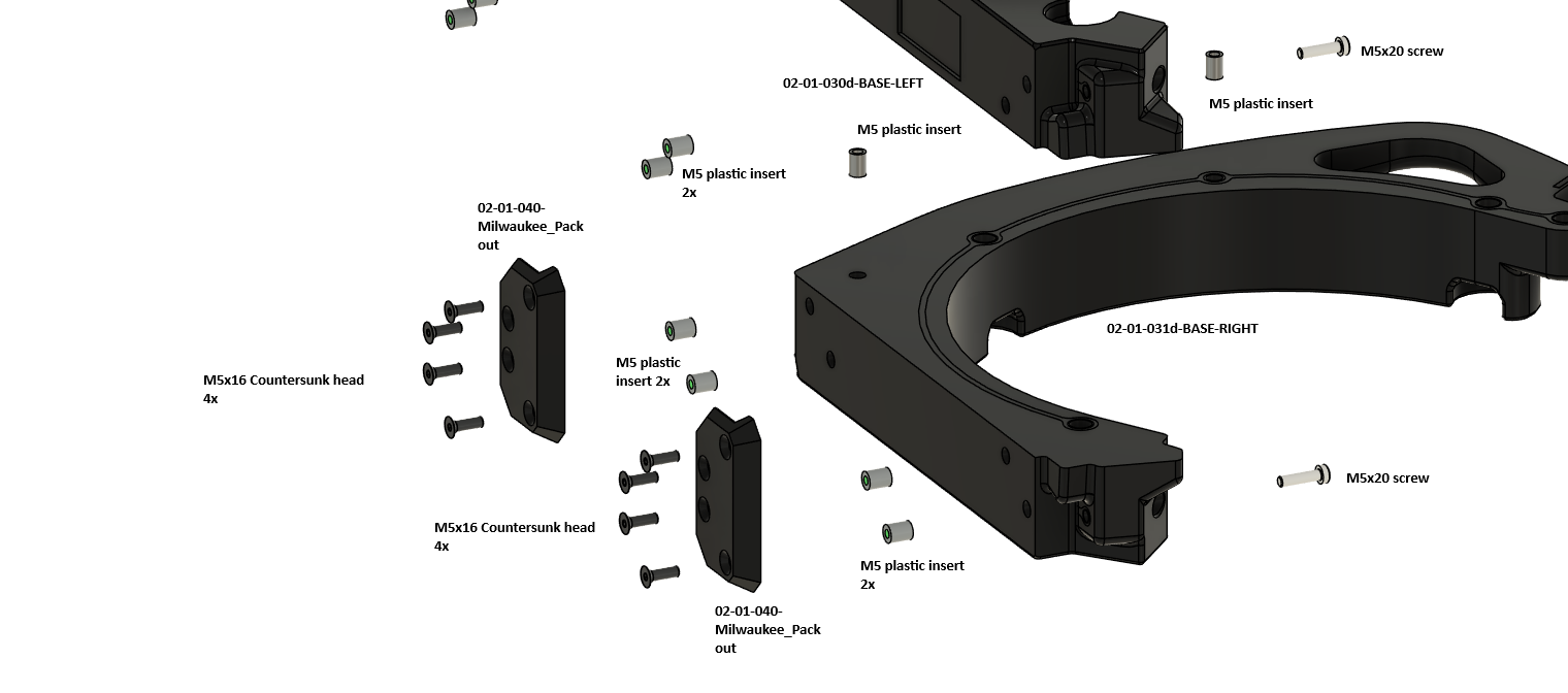
Press M5 inserts into the bases 02-01-030d-BASE-LEFT and 02-01-031d-BASE-RIGHT. Screw each holder 02-01-040-Milwaukee_Packout to its base with four M5x16 countersunk screws and join the bases with M5x20 screws.